Note
This technote is a work-in-progress.
1 Abstract
For the AuxTel Calibration Illumination system, we plan to use a LabJack T4 to control and communicate with the KiloArc White Light Source. We will use the same LabJack to control the Linear Actuator which opens the shutter for the beam. Below is a description of the I/O for the LabJack and corresponding rules for the operation of the elements described.
When the White Light Source (WLS) is being operated, a Chiller must also be running to cool the beam. The chiller will not be controlled using the LabJack but rather a Serial Device Server (Nport 5150A). Some of this had previously been implemented in a CSC for control by the ADAM-6024. The code can be found here: https://github.com/lsst-ts/ts_ATWhiteLightSource. Included below are some rules about operating the WLS with the Chiller.
2 Overview
2 main elements will be controlled with the LabJack T4: KiloArc White Light Source and a Linear Actuator/Shutter. In addition to the LabJack T4, we will also use an expansion board, which is a modified version of the LabJack CB15 Terminal Board. This expansion board was designed and built by Oliver Wiecha.
Outputs:
[DAC0] - KiloArc power level; voltage steps for input values (DAC0)
[5V] – Output for optical encoder (on expansion board)
Inputs:
[FI04] – Error message
[FI05] – Cooldown status
[FI06] – Standby status
[FI07] - Error status (i.e. an error exists)
[EI04] – Shutter open status
[EI06] – Shutter closed status
[EI03] – Linear actuator move. If linear actuator is on, shutter will open or close
[EI02] - Linear actuator on/off. If low, linear actuator can move
[EI00] – Optical feedback for Linear actuator
3 KiloArc
Some of this information is repeated from a couple documents on docushare:
3.1 Outputs:
The power of the bulb in the KiloArc can be controlled using an analog output on the LabJack. There are three operating modes: Off, On (minimum), On (adjusted). They each have a unique input voltage range.
Off/Cool Down mode (lamp is off): 0 V to approximately 0.803 V
On (minimum @ 800W): 0.941 – 1.941 V
On (adjusted 800 – 1200 W): 1.961 – 5V. There are 155 steps possible, each corresponding to 0.0196V
3.1.1 Rules:
After the system is powered on, the lamp should remain in “cooldown mode” for a minimum of 15 minutes to allow the mercury to evaporate completely. The fan will be running during this time.
When turned off, do not re-ignite the lamp for a minimum of 15 minutes to allow the mercury to condense completely within the lamp bulb. The fan will be running during this time.
If any error condition occurs, including pressing the red EMERGENCY SWITCH (triggered by a fuse), the lamp will immediately extinguish the bulb and keep checking to see if the error has cleared.
Note: Once an error is removed, there will likely be an error condition #4 generated and this will clear after a few seconds and the lamp will enter cooldown mode. Operation of the lamp system via normal program control may then proceed.
The Chiller must be on and circulating water before the WLS can be moved to ON mode.
If the Chiller has an error message, the WLS must be moved to the OFF mode. This includes all temperature errors.
3.2 Input:
There are 4 output channels that the KiloArc communicates with. Three of them just send a status (Boolean) and one will send error messages. On the back of the WLS there are two LEDs: one for status and one for the error message. When an error is present, the status LED will be red and the error LED will pulse the code. Otherwise, only the status LED will be illuminated.
For all of these inputs, we will use flexible I/O, which are configurable 0-2.5V digital I/O. The status lines have been measured to be high at 1.8-2V. Below, the physical wire colors are identified in parentheses. Ground is the black/shield and all other wires are for specific status lines.
[FI07] - Error status (i.e. an error exists) (Red wire; red status LED)
[FI06] – Standby status. (Green wire; green status LED)
[FI05] – Cooldown status. (Brown wire; blue status LED)
[FI04] – Error message. (White wire; Red error (blinking) LED)
3.2.1 Status:
Error: When the system is in an error state, the status LED will be red. The actual error will be blinked on the error LED, which is separate.
Standby: This mode occurs when the cooldown mode times out waiting for a start operation. The blower is off, there is no Error. When a start operation is received, the blower is turned on, then after a 3 second delay, the lamp ignites the bulb and the lamp system is put into operating mode. This will show a greed LED.
Operating: The blower is on, the bulb is lit, and there is no Error. From here, the user may extinguish the lamp, or adjust the light output. The status LED will be blue as the fan will be running.
Cooldown: This condition occurs whenever the unit is first powered on, and whenever the lamp extinguishes the bulb. Cooldown mode is a mode when the blower is running, and the lamp is waiting for a start operation. There is no error. The lamp system will stay in this mode until the internal timer times out (a couple of minutes), an error occurs, or the lamp receives a start operation. If a timeout occurs, the blower is turned off, and the unit is put in standby mode. Blue LED will be illuminated.
3.2.2 Error:
All error codes are 1⁄2 second on, 1⁄2 second off, repeating for the number of times as the code number, then 1 1⁄2 second off before repeating the cycle. Code numbers:
#1 EMERGENCY KILL SWITCH TRIGGERED
#2 TEMPERATURE SWITCH FAULT CHASSIS OVERHEATING
#3 ACCESS DOOR SWITCH NOT SET
#4 LBM_HOT FROM BALLAST INDICATES BALLAST OVERHEATING
#5 USB CABLE REMOVED - DISCONNECTED FROM HOST COMPUTER
#6 AIRFLOW SENSOR DETECTING INADEQUATE COOLING DUE TO LACK OF AIRFLOW
#7 BULB DIDN’T EXTINGUISH AFTER INSTRUCTED TO DO SO. ENGAGE EMERGENCY KILL SWITCH, WAIT 5 MINUTES, THEN TURN OFF POWER. RESTART SOFTWARE, WAIT 1 MINUTE. TURN ON POWER
#8 AIRFLOW CIRCUITRY MALFUNCTION
For error codes 1, 2, 3, 6, and 8: (not much that can be done here in software) • If the error was detected when the bulb was not illuminated, the error may be cleared by resetting the emergency kill switch, and the it will go into cooldown mode. Operation of the lamp system may proceed. • If the error was detected when the bulb was illuminated, the Emergency Kill switch must be reset (pull the Emergency Kill switch out from the lamp unit), the error indicator will stop, but the status will indicate that the start process needs to be recommenced.
4 Linear Actuator circuit:
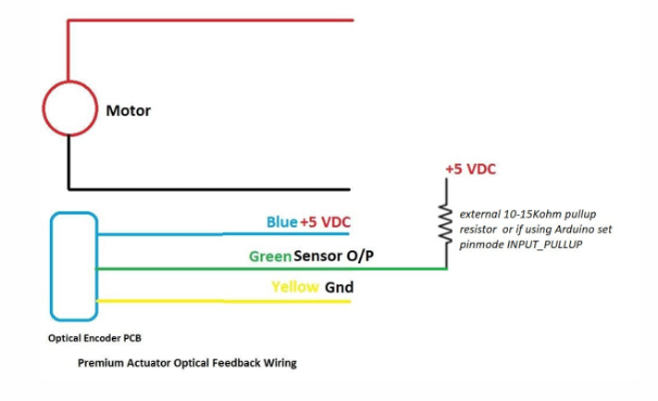
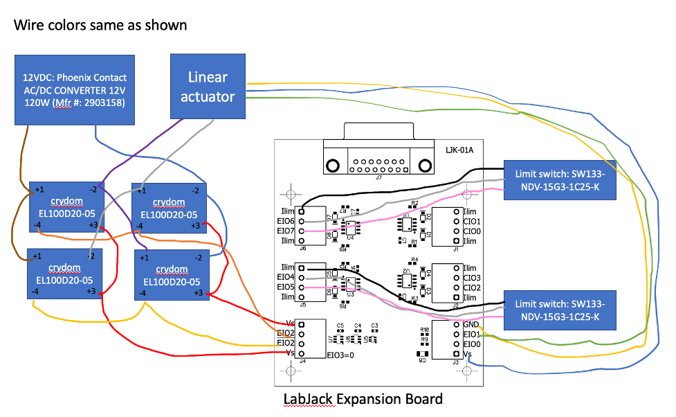
The linear actuator is a Firgelli Optical Feedback Linear Actuator (Firgelli FA-OS-35-12-18). It is powered by 12V and will be operated to be either completely open or closed. This is operated with a double-pull double-throw series of solid state relays. There is an optical feedback circuit on the linear actuator that sends a signal when it moves a certain distance. Unfortunately, it does not give an absolute distance (i.e. just a step counter). This optical feedback requires 5V. Additionally, there are 2 limit switches in this circuit to indicate when the actuator is fully open or closed.
4.1 Parts Used:
12V power supply: Phoenix Contact AC/DC CONVERTER 12V 120W (Mfr #: 2903158)
Solid state relays x4: crydom EL100D20-05
Limit switches: SW133-NDV-15G3-1C25-K
4.2 Output:
[5V] - Optical Feedback (on expansion board)
4.3 Inputs:
Digital I/O inputs:
[EI04] – Shutter open when high
[EI06] – Shutter closed when high
[EI03] – Linear actuator on/off. If low, linear actuator can move.
[EI02] – If EI03 is low, when high shutter closes and low opens shutter [0=open; 1=close]
[EI00] – Optical feedback for Linear actuator (pink cable -> blue LS; gray cable -> green LS; shield cable -> yellow LS)
4.4 Connector:
This connector includes the optical feedback wires as well as the power cable. The index indicates the hole numbered on the actual connector. The first element listed is on the linear actuator side and the secon (->) is on the electronics cabinet side.
Positive -> Black
Negative -> White
Green -> Gray
Yellow -> Shield
Blue -> Pink

Figure 1 Optical Feedback Wiring Diagram from Vendor

Figure 2 LabJack Expansion Board Wiring Diagram